Magnetic Shielding Design for Manufacturing
Magnetic shielding for static and low frequency (<100 kHz), time-varying magnetic fields is accomplished by containing a specific device or item within a sheet metal enclosure of high permeability material. Typically, a sensitive electronic component requires magnetic shielding protection from nearby transformers or power supplies radiating a potentially troublesome magnetic field. High permeability material is a nickel iron alloy consisting of 50 to 80 percent nickel. Initial static permeability values are in excess of 60,000. Permeability is defined as a ratio of the flux induced in a material (expressed as B, measured in Gauss) proportional to the ambient or applied magnetic field (expressed as H, measured in Oersted). As a reference, the initial permeability of a material is defined as the ratio of the induced flux B in the material divided by the ambient Earth’s magnetic field, H (approximately .50 Oersted). The high ratio indicates the material’s ability to induct magnetic flux. The simple B-H Graph shown in Figure 1 is used to determine a material’s permeability and resultant magnetic shielding performance. The orange line on the B-H Graph represents the function of high permeability material at DC and 60 Hz. The permeability value is equal to the derivative of that function. Note that as the applied field increases beyond the steepest slope, the permeability starts to decrease. This change is known as the saturation point of the material. Once the material becomes fully saturated, it offers no magnetic shielding protection as the derivative asymptotically approaches zero.
Magnetic Shielding Design for Manufacturing
Figure 1. B–H graph used to determine a material’s permeability.
.
In most shielding applications, the specified shielding alloy is between .004″ and .120″ thick sheet metal. Thicker materials can be milled from bar stock. High permeability magnetic shielding alloys are produced by several steel mills worldwide.
FABRICATION
The typical magnetic shield design requires sheet metal fabricating and metal forming techniques. Shielding shapes include simple sheet metal cylinders, complex weldments, and precision machined housings. But in almost all cases an application involves an enclosure type design. Since magnetic flux will follow the path of least reluctance, the high permeability of the enclosure shape absorbs and shunts the magnetic flux, leaving the inside of the enclosure with a lower or attenuated magnetic field. The shield enclosure can also work the other way by containing a magnetic field within the enclosure boundary.
Once a shield enclosure is designed for shielding effectiveness, a mechanical design application is needed. A simple cylindrical shape is often the most effective shield and the simplest to fabricate. Sheet metal is rolled, and a seam can be butt welded or can be overlapped and spot welded. The mechanical forming constraints of high permeability alloys are very similar to those of stainless steel.
Figure 3. Fusion welded seams are TIG (Tungsten Inert Gas) welded.
Other typical shapes are similar to electronic chassis where a prefabricated flat panel is formed using a conventional sheet metal press brake and associated forming equipment. Complex assemblies can be fusion welded (Figure 2) or spot welded or can be attached with mechanical fasteners.
CYLINDERS
Figure 2. High permeability alloys laser machine readily.
The simplest and most effective shape for a magnetic shield is a sheet metal cylinder made of a high permeability material. A machine known as a slip roll or pinch roll is employed. The material is pinched between two rollers. Motion is applied and the material is then pushed against the forming roll. The resultant diameter of the finished cylinder is determined by the position of the forming roll relative to the pinching rolls. After the cylinder is roll formed to shape, the seam can be overlapped and spot welded or butted and fusion welded.
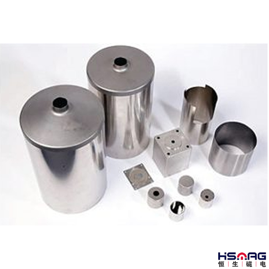
Figure 4. Typical shapes for magnetic shields are cylinders, cans. and rectangular enclosures. The covers for the cylinders were spun to shape.
A spot weld is a simple electrical resistance weld, and a butt, fusion weld is usually accomplished via a process known as TIG (Tungsten, Inert Gas) welding. The inert gas used is argon, and it serves to prevent oxidation and carburization of the material for the brief time it is in a molten state. Laser and electron beam welding can also be used (Figure 3). High permeability alloys weld quite well, and demanding mechanical tolerances can be achieved with proper weld fixturing.
Figure 5. A small cover is spun to shape.
Figure 5. A small cover is spun to shape.
SHAPES
Boxes and chassis shapes are achieved using a pre-cut blank and a typical press brake. Usually a part is developed in a flat pattern layout, which can then be laser machined or punched in a CNC punch press. Subsequent forming operations are done in a press brake. Corners and seams can be left open or can be welded shut depending on the application. In high volume applications, tooling can be designed that will pre-cut and form the blank in a single operation.
Figure 6. Examples of spun parts.
METAL SPINNING & HYDROFORMING
When stringent mechanical tolerances are required, metal spinning and hydroforming can be utilized. Metal spinning, as the name implies, involves rotating the material in a lathe and using a forming role to flow the metal against a mandrel. See examples in Figures 4, 5, and 6. The mandrel is a machined tool made to conform to the inside profile of the desired finished sheet metal part. The forming roll is usually controlled by an operator (spinner). Spinning metal requires a great deal of experience. If forced too far, the metal will crease or tear because of work hardening. Often the metal will require in-process annealing to relieve mechanical stress, and additional spinning can then occur. Of course, spinning can only be used on parts that are round or conical. The advantage of spinning is low tooling costs as mandrels are often made from wood or aluminum.
Hydroforming involves a simple tool machined to the inside dimensions of the part and a hydroform machine. The hydroform pushes the tool into a rubber diaphragm behind which hydraulic pressure forces the sheet metal to wrap around the tool. In addition to round parts, many unique shapes can be made by hydroforming. Hydroform tools are made from tool steels and other materials such as kirksite, a zinc alloy that can be cast into unique shapes (Figure 7).
Figure 7. The hydro-forming process.
Hydoformed and spun parts usually require a final trimming operation to remove excess material and/or to add detail. Most trimming operations can be accomplished on laser, milling, or shell trimming machinery.
HEAT TREATING
Figure 8. The large grain size is evident after heat treating.
The final step in manufacturing magnetic shielding parts is heat treating. Cold working and machining will have rendered the grain structure of the material in a less than ideal shielding condition. High permeability material is best heat treated in a dry hydrogen atmosphere, or vacuum furnace. Hydrogen is preferred as hydrogen gas will help remove any carbon or oxygen impurities. The material is brought up to 2100 degrees F and held for two to four hours. The furnace is then cooled at a specific rate to optimize grain growth and reordering. A large, well ordered grain will yield maximum permeability resulting in optimum shielding (Figure 8).
CONCLUSION
Magnetic shielding characteristics are optimized if welding can be avoided. The shield designer should strive to minimize welded sections and to allow generous forming radii. Magnetic flux leakage will occur at sharp corners effecting overall shield performance. The most efficient magnetic shield geometry would be a spherical shell. Since spherical shells are difficult and costly to form, the next best design is a simple cylinder. Rectangular boxes and chassis, although not optimal, will perform adequately as magnetic shields. The design engineer has a degree of flexibility when optimizing a design. Unlike RFI shields where holes and apertures are discouraged, magnetic shields can have holes and openings although it’s best to minimize their number. In recent years, FEA (finite element analysis) modeling of magnetic shield designs has recently become very helpful and has aided in the design process described here. Since the proof is in the prototype and since so many extenuating circumstances can affect shield performance, it’s best to try one on for form, fit, and function first.
Bonded NdFeB Magnets and Assemblies
Sintered NdFeB Magnets and Assemblies
Strong NdFeB Magnetic Lifter PML3000A
Powerful Magnetic Lifter PML2000A
New Product 13000Gs Magnetic Rods!
Sintered NdFeB Magnetic Mounting Hook Ø48 mm